|
| Main Page |
 |
N322Z
sitting at the hangar ready to go |
 |
N322Z
featured in KitPlanes magazine |
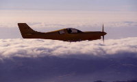 |
N322Z
at dusk Low clouds and fog of the San Francisco area provide a backdrop for a silhouette of N322Z |
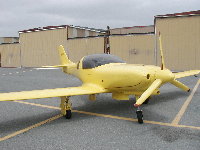
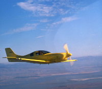 |
N322Z
on a clear day It's not always foggy in the San Francisco Bay Area-blue and yellow make a nice combination. If you look closely, you will see that the pilot is in the right seat. Not so. This was scanned from a color slide which was mounted back side up in the scanner thereby reversing the image. |
 |
N322Z
at Oshkosh This photo was taken by FLYING magazine at Oshkosh and was published in their November, 1993 issue. They were kind enough to send Will (the builder) a large glossy print. N322Z has visited Oshkosh three times. |
|
|
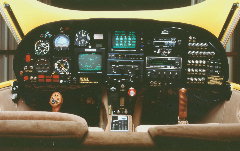
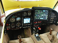
Glass
Panel |
 |
ICDS 2000 display Display options of the Arnav "big-screen" ICDS 2000 allow you to show your moving map with sectional detail. This photo is a screen shot of a trip from Oakland to Reno. Notice both cities and airports are clearly identified. For more about this, visit the Arnav Web site. |
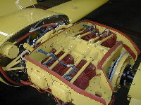 |
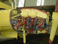
Engine The engine is a Lycoming O-360 with an Ellison throttle body; it has been flowed and ported by Lycon (Visalia, California) and fitted with 9.5/1 pistons. This amazingly smooth engine produced 226 horsepower on the dyno. If you look closely you see a wire coming from the oil filler cap. The oil dip stick is actually a capacitor gauge with a thermocouple on the end. The display unit in the cockpit shows the oil level (in quarts) and the oil temperature. The oil level reading is highly accurate. In flight it reads one and one half quarts lower than when the engine is not running. That reflects the amount of oil being circulated within the engine. Both the engine and the baffling are powder coated yellow-the same color as the airplane. |
 |
|
|
Cowling The cowling is attached to the fuselage and the two halves held together with hinge pins-no unsightly row of screws. |
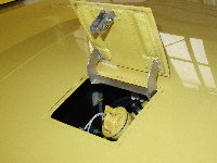 |
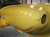
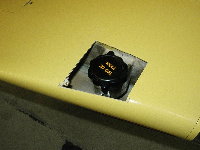
Oil
filler door The oil filler access door hinge is designed to give a smooth, hardware-free surface when closed. It is spring loaded and opens with a release handle just inside the right air intake. |
 |
|
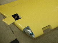 |
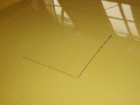
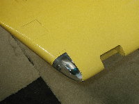
Fuel
filler No unsightly fuel filler caps on this wing. The extended-range tank and standard tank (20 gallons on each side) are interconnected and fill from this covered wing-tip filler. When closed, the sliding door is barely noticeable. Also visible in these photos are the position lights and the right landing light. |
 |
|
 |
|
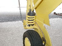 |
Main
strut The rubber donuts spring/shocks included with the kit provide next to zero in the spring category (about the only spring action you get is from the tires). The unit shown is from Spy Aircraft Systems (in New Zealand); it consists of a coil spring and a damper (shock absorber). It makes a HUGE difference in landing-much easier to nail it. |
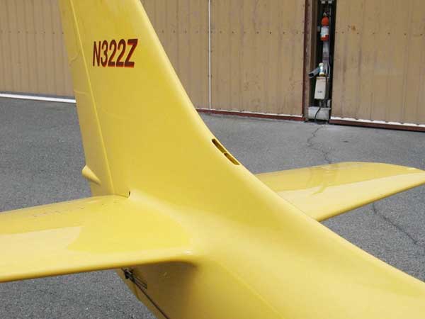 |
Air
vent There's nothing quite as nice as cool air on the back of your head on a hot day. For this, cooling air is taken in by this opening in the vertical stabilizer and ducted forward. It is discharged through two eyeball vents behind the aircraft's occupants. You can see them in the close-up of the ski rack |
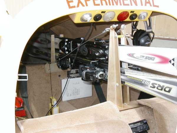 |
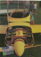
Ski
rack The builder was an avid skier, so a ski rack was a must. With this set up, two pair of skis are anchored solidly between the pilot and passenger. With the rear of the binding snug against the forward rack, the ski cg is only about 12 inches behind the edge of the seat so they create no weight/balance problem. |
 |